Introduction
Hello and welcome to a new quick start guide on how to best use Movicon.NExT™.
In this tutorial we will create an example using a major part of the feature offered by the Movicon.NExT™ platform.
Procedure
The application
· This example is very simple: we
will place a tank on the main screen to fill up with liquid whose
level and temperature will be monitored while doing so. The tank will start to fill after
the operator has activated the motor.
This application
will be created with 7 screens:
- Main: this is the application’s main screen.
- Alarms: this screen shows a summary of active alarms by using the Alarm Window object.
- Grid: the tank level history will be displayed in this screen by means of using a DB Connector Grid object.
- Motor_Popup: this popup contains the motor’s start and stop commands.
- Trend: the Data Analysis Trend object will be used in this screen to display the historical trend of the temperature while in operation.
- _Bottom_Layout: this is a layout screen which is inserted at the bottom of the video screen. In this screen we will insert some buttons which will be used to navigate through the screen pages.
- _Top_Layout: this layout screen is inserted at the top of the video screen. In this screen we will insert a clock to display the system’s time, an alarm banner to display the last alarm detected by the system, and a button to close the application’s runtime.
Creating the application
Now, let’s start creating
the application..
First startup the development environment by double-clicking on the
Movicon.NExT icon.
The editor will open showing the Startup Page. To create a new
Movicon.NExT project, click on the Empty Project Wizard.
This will startup the New Project Wizard.
The first window shows three project architecture types to choose from.
Select the Distributed Project option and leave all the fields
that appear when doing so set for default. Click on the Next Step
arrow to continue configuring the project.
Enter a name for the project in the Name textbox. In our example, we
shall call it Tutorial. Leave the Path where to save the files set
for default and make sure that the Local File has been selected. Click
on the Next Step arrow to continue.
Click Finish to terminate the project configuration procedure.
Once the application has been created, it will appear in Design mode
on your video screen.
Let's start by creating the skeleton of our application which will
consist of:
- Tags: these are the project's variables.
- Historian: this is the component which records the tank level and temperature trends when in operation.
- Alarms: by means of referring to the set alarm thresholds, we will be able to find out whether the temperature is in the optimal range or not while in operation.
Creating tags
Now create a tag as follows:
- Open the I/O Data Server in the project tree within the Project Explorer window.
- Go to the Tag List by selecting appropriate I/O Data Server tab.
- Right click on the workspace and select the Add New Folder. Once created, change its Name property to Tank.
- Select and right click on the Tank folder. Select the Add New Tag item from the contextual menu that appears.
- Configure the tag in the following way:
- Name: CmdOnOff
- Model Type: Variable
- Data Type: Boolean
- Confirm these changes by clicking on the Accept Changes icon on the toolbar at the top of the Properties window.
Create another three tags by using the same procedure we used for the first tag and configure them in this way:
| Name | Level |
| Model Type | Variable |
| Data Type | Int16 |
| Name | SetPoint |
| Model Type | Variable |
| Data Type | Int16 |
| Name | Temperature |
| Model Type | Variable |
| Data Type | Int16 |
Creating the HIstorian
We shall now go ahead and create the Historian.
To create the Historian, open the I/O Data Server and:
- Click on the Historian tab to open it.
- Right click within its workspace and select the Add New Historian option from the contextual menu that opens and configure it.
- Configure the Historian in this way:
- Historian Name: Historian
- Enabled: Active
- Deviation Type: Absolute Value
- DB Connection String: click on the properties corresponding three dots and use the wizard to configure the connection string towards database contained in the PC's SQL Server instance.
Assign the Level and Temperature Tags to the newly created and configured
Historian.
To assign the tags to the Historian, proceed as follows:
- Select and right click the newly created Historian.
- Select the Assign Tag option to insert the project tags in the Historian.
- Select the Level and Temperature Tags contained in the Tank folder and click the OK button to confirm.
Creating the Alarms
The temperature alarms are the last components we are going to create
in our example. These alarms will be created within the I/O
Data Server.
To create an alarm, open the
I/O Data Server and:
- Go to the Alarms Tab by selecting the corresponding I/O Data Server tab.
- Expand the Alarm folder in the Alarms tab until you reach the source item.
- Select the source and right click to open the contextual menu.
- Select the Add New Alarm Definition from the menu. Configure the alarm in this way::
- Name: TemperatureAlarmHiHi
- Alarm Type: Exclusive Level
- Severity : 100
- Alarm Limits
- Enable High-High Limit: Active
- High-High Limit Value: 180
Create another three alarms with the same procedure used for the above alarm by configuring them in this way:
| Name | TemperatureHi |
| Alarm Type | Exclusive Level |
| Severity | 100 |
| Alarm Limits > Enable High Limit | Active |
| Alarm Limits > High Limit Value | 150 |
| Name | TemperatureLo |
| Alarm Type | Exclusive Level |
| Severity | 100 |
| Alarm Limits > Enable Low Limit | Active |
| Alarm Limits > Low Limit Value | 100 |
| Name | TemperatureLoLO |
| Alarm Type | Exclusive Level |
| Severity | 100 |
| Alarm Limits > Enable Low-Low Limit | Active |
| Alarm Limits > Low-Low Limit Value | 50 |
Assigning tags to alarms
Now we shall create and configure four tags and assign them to the alarms:
- Select one of the newly created alarms from the I/O Data Server's Alarms pane, for example the TemperatureAlarmHiHi Alarm.
- Right click it and select the Assign Tag option.
- Select the previously created Temperature Tag form the table that appears and click OK to confirm.
Creating a simulation
Now that we have created the application's skeleton, we can now
run a simulation to test its data.
The simuation is run with a script. The script is divided into
different sections:
- Sub Main: this is the main procedure. It effectively runs the script.
- Public Function FillTank(): this is the function that executes the filling of the tank.
- Public Function Temperature(): this is the function that executes the temperature simulation.
- Public Function GetRandomNumber(myValue): this is the function that returns a random number multiplied by the value passed as argument.
- Select the Scripts resource from the project tree in the Project Explorer window.
- Right click it to open the contextual menu and select the New item.
Double-click the script to open it and insert the source code (the code has been divided into sections for simplicity):
- Constant
definition section:
'#Language "WWB.NET"
Option Explicit
Const STEP_TIME_SIMULATION As Integer = 25 'sec
Dim bClock1sec As Boolean
Dim bClock10sec As Boolean
Dim bClockXsec As Boolean
- Sub
Main:
Sub Main Handles .Main
Dim tTimeClock1sec As Date
Dim tTimeClock10sec As Date
Dim tTimeClockXsec As Date
Try
'*** General Simulation
tTimeClock1sec = Now
tTimeClock10sec = Now
tTimeClockXsec = Now
Do
If DateDiff("s", tTimeClock1sec, Now ) >= 1 Then 'Contatore 1 secondo
bClock1sec = True
tTimeClock1sec = Now
Else
bClock1sec = False
End If
If DateDiff("s", tTimeClock10sec, Now ) >= 20 Then 'Contatore 10 secondi
bClock10sec = True
tTimeClock10sec = Now
Else
bClock10sec = False
End If
If DateDiff("s", tTimeClockXsec, Now ) >= STEP_TIME_SIMULATION Then 'Contatore Toggle
bClockXsec = Not bClockXsec
tTimeClockXsec = Now
End If
'aggiornamento valori ogni secondo
If (bClock1sec = True) Then
Call FillTank()
Call Temperature()
End If
DoEvents
Loop Until ScriptDocument.IsInStoppingMode
Catch Exep As System.Exception
Debug.Print "Error Main Sub: " & Exep.Message
Finally
End Try
End Sub
- FillTank()
Function:
Public Function FillTank()
If (Tank_CmdOnOff = True) Then
Do
Tank_Level = Tank_Level + 1
Loop Until Tank_Level <= Tank_SetPoint
If Tank_Level = Tank_SetPoint Then
Tank_Level = Tank_Level
Tank_CmdOnOff = False
End If
End If
End Function
- Temperature()
Function:
Public Function Temperature()
Tank_Temperature = GetRandomNumber(2)
End Function
- GetRandomNumber(myValue)
Function:
Public Function GetRandomNumber(myValue As Integer)
GetRandomNumber = Int(100*Rnd)*myValue
End Function
Creating the screens
Now that we have finished writing code for simulating data, we will
create the screen that we need.
First we will create the _Layout_Top
layout screen as follows:
- Select the Screen resource from the project tree in the Project Explorer Window.
- Right click it and select the New option from the menu that appears.
- A popup will appear allowing you to configure the screen's main properties. Configure the screen as follows:
- Length: 1920
- height: 100
- Name: _Layout_Top
- Click OK to confirm.
- Select the Screen resource from the project tree in the Project Explorer Window.
- Right click it and select the New option from the menu that appears.
- A popup will appear allowing you to configure the screen's main properties. Configure the screen as follows:
- Length: 1920
- height: 100
- Name: _Layout_ Bottom
- Click OK to confirm.
- Look for the Screens resource in the project's tree structure in the Project Explorer window and select it.
- Right click it and select the New option from the menu which opens.
- A New Screen popup will appear which will allow you to set the screen's main properties. Configure the screen as follows:
- Width: 1920
- Height: 880
- Name: Main
- Click the OK button to confirm the configuration.
Repeat the procedure used to create the Main screen to create a
screen for the Alarms, Grid and Trend.
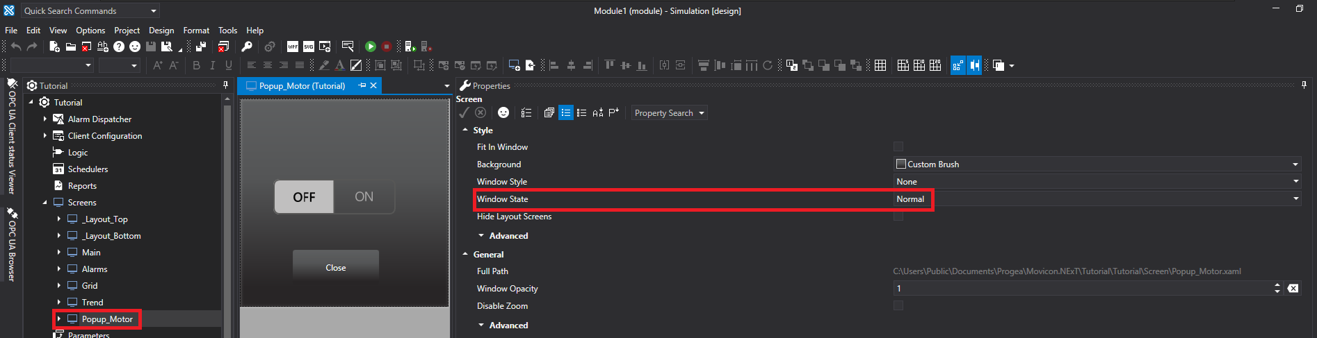
This last screen we shall create in this way:
- Length: 300
- Height: 300
- Name: Popup_Motor
- Window State: Normal
Configuring the project startup properties
Now that the screens have been created, we can continue onto the next step to change the project's properties by entering the Main screen we just created as the project's Startup screen. Therefore:
- Select the name of the project from the application's tree structure.
- Open the Properties window.
- Change following project's properties as follows:
- Startup Page Type: Main Screen
- Startup Screen Name: Main
Enter the Simulation script from the Startup Scripts List in the same properties section as follows:
- Go to the Startup Scripts List property found in the Project Startup Advanced group properties. Click on the three dots corresponding to the property to open the popup containing the list of scripts to startup.
- Once opened, click on the Add New button to open another popup with a list of script to choose from.
- Select the Simulation script from those available and click OK to confirm.
- Once the script has been inserted on the list, check that its execution mode is Normal.
- Confirm the selection by clicking the popup's OK button.
Now that we have finished configuring the project startup, save the project by clicking on the Save All icon on the Movicon.NExT Editor's toolbar at the top.
Creating the navigation menu
Make sure that the _Layout_Bottom screen is open, click on the Toolbox
tab on the editor's far right next ot the Properties Window to open
the Toolbox library provided by Movicon.NExT.
Drag a Standard Metro Style button from the Button category's Standard
subfolder onto the screen.
Associate the Main screen to the button by dragging it from the screen
list onto the button.
Repeat this procedure to create buttons that call the Alarms, Trend
and Grid screens.
Creating the top bar
We shall now creat the application's top bar.
Open the _Layout_Top screen and click on the Toolbox tab on the
editor's far right next ot the Properties Window to open the Toolbox
library provided by Movicon.NExT.
Drag a Standard Metro Style button from the Button category's Standard
subfolder onto the screen.
Open the Properties Window and enter the Close Runtime String in the
Text property.
Select the previously inserted Button and open the Commands tab found
at the bottom of the editor. Select the System Commands item
from those available on the list. Once selected and added to the list
of commands associated to the graphical object, check that the Command
Type is inserted as Quit Runtime Execution.
Drag and place the Digital Clock object, which can be found in the Clocks folder, and the Alarm Banner object, which can be found in the Alarm Viewers folder, on the same screen.
Select the Alarm Banner object and open its Properties Window. Look for the Area/Source Filter property and configure it by selecting Area from the combobox which appears when clicking on the property's corresponding three dots.
Creating the Trend window
We will now build the Level Trend window.
Open the Trend window and drag the Data Analysis Trend from the Trends
folder and place it on the screen and enlarge it.
Now lets configure the object:
- Select the newly inserted Data Analysis Trend object and open its Properties Window.
- Look for the Object Configuration property found in the Data Analysis - Settings section. Click on the three dots corresponding to the property to open its Smart Properties to insert pens, and then the tags, in the Trend.
- Click on the + button to add a pen.
- Select a color, red for example, and add Temperature as the name to use in the Name texbox. Then add the Tank\Temperature variable by selecting it from the Variable's combobox.
- Check that the Visible and Automatic Scale properties are enabled, and that the Min and Max properties are set to 0 and 200 respectively.
- Click OK to confirm.
Creating the Alarm Window
We will now build the window with the Alarm Window object.
Open the Alarm Window and drag the Alarm Window object from the Alarm
Viewer folder and place it on screen and then enlarge it.
Leave its configuration set for default to view active active alarms
in the application.
Creating the Popup_Motor Window
We wil now create the Popup_Motor window.
Make sure that the Popup_Motor window is open and drag the Horizontal
Switch from the Switches folder's Flat Toggle Switches subfolder and
place it on the screen.
Associate the Tank\CmdOnOff tag to the graphical object by dragging it from the Tag List onto the object.
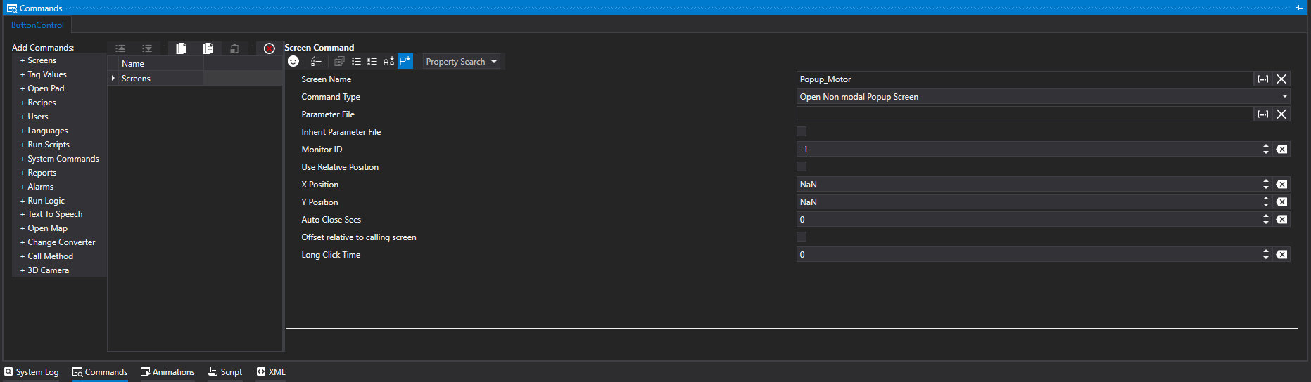
Drag a Standard Metro Style button from the Button category's Standard subfolder onto the screen.
Select it and:
- Go to its Properties Window and change the Text property by inserting the Close String.
- Go to the Commands tab, selet the Screen command and configure it as follows:
- Screen Name: Popup_Motor
- Command Type: Close
Building the Grid window
Now, we shall build the Grid window.
Make you that you have opened the Grid window. Drag the DB Grid Control
from the DB Connects folder and place it on the screen.
Configure the object as follows:
- Select the previously inserted DB Grid Control on screen and open its Properties Window.
- Look for the Object Configuration property found in the DB Connector Grid property group. Click on the property's three dots to open its Control DataSource Editor window.
- Click on the Control DataSource Editor button to insert the query.
- Click on the Connection properties three dots to the right to open the Wizard used to create the connection string towards the application's Tutorial_IOServer database.
- Once you have configured the connection string, click on Test Connection to check to see if it works and then click on OK to confirm everything.
- Click on the Selection property's three dots to open a Wizard to select the database table and columns. Select the UFUAAuditDataItem table and following columns:
- Name
- RecordDateTimeUtc
- SourceTimeStamp
- ServerTimeStamp
- UserName
- Reason
- EventId
- Once the table and columns have been selected, click OK to confirm it all.
- Click on the Where property's three dots to open the Wizard needed to create the query's Where filter. Click on the + button next to And and select the following parameters:
- Name
- Contains
- Level
- Now that the filter has been configured, click on OK to confirm it all.
- Click on the Group by property's three dots to open the Wizard needed to select which Group by field and sort to use. Select the RecordDateTimeUtc as the Group by field and Ascending as order.
- Now that we have configured the Group By and Sort fields, click OK to confirm the query configuration.
- Click OK to confirm each popup that is open until they are all closed.
Creating the Main window
Now,
we shall create the Main window.
Make sure the Main window is open and insert the following graphical
objects from the Toolbox Library:
- Three displays from the Display folder. Associate the Tank\SetPoint, Tank\Level and Tank\Temperature tags to the displays.
- A Transparent Vertical Indicator from the Bargraphs folder. Associate Tank\Temperature tag to the object.
- A Standard Metro Style button from the Buttons folder's Standard subfolder. Associate the Popup_Motor screen to the button and change the Command Type to Open Non-modal Popup Screen.
- A RealTime Trend object from the Trends folder.
Configure the RealTime Trend object in the following way:
- Go to the object's Properties Window and look for the Object Configuration property found in the Trend - Settings property group. Click the property's corresponding three dots to open its Smart Properties window to insert the pens, and then the tags, in the Trend.
- Click on the + button to add a pen.
- Select a color, such as red for example, and add the Temperature name in the Name textbox. Then select the Tank\Temperature variable from the Tag Name combobox.
- Check that the Visible and Automatic Scale properties are enabled, and that the Min and Max properties are set to 0 and 200 respectively.
- Click OK to confirm.
Make sure that the Main window is open and insert the following graphical objects from the Symbol Library:
- A Tank object from the Tanks>Analog Animated folder section. Associate the Tank\Level tag to the object.
- A Motor 11 object from the Motors\Digital Animated folder section. Associate the Tank\CmdOnOff tag to the object.
Connect the tank and the motor by using the pipes found in the Pipes folder. Associate an animation to each one of these objects as follows:
- Select the object and open the Animation tab.
- Select the Back Color animation to associate to the graphical object and add it to the Animation List with a double click.
- Configure the animation by entering the Tank\CmdOnOff tag in the Tag property and the colors as follows:
| Valore | Colore | Tempo Lampeggio | Colore Lampeggio |
|---|---|---|---|
| 0 | Transparent | 0 | Default |
| 1 | Green | 0 | Default |
Save the project by clicking on the Save All icon on the Movicon.NExT Editor's toolbar at the top.
Now
lets test everything in runtime mode by clicking on the Start Runtime
icon.
As soon as the project starts up in runtime, you will see that the
temperature has simulated values reported on the Trend. Enter a positive
value other than zero in the Display object linked to the SetPoint.
Then click on the Motor Commands button to display the Popup_Motor
window. Click on the switch in this window to turn on the motor and
see the level rise.
Navigate through the pages to explore the Alarms, Temperature and Level Historians.