Movicon.NExT Help on Line - Rel. 4.2.358
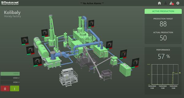
Movicon.NExT uses XAML graphics with WPF technology to allow you to insert and use objects with 3D graphics. Each individual 3D symbol component of the object can be animated and the object's observation angle can also be varied (camera).

This diagram illustrates the concepts used for managing 3D objects within the Movicon.NExT screens. The system accepts previously created 3D models that have been made available for importing to Movicon screens with the aim to render the screens dynamic and interactive with the visualization and supervision system users.
Once a 3D model has been inserted, it can be associated with project tags in order to manage the dynamic animation functions. These functions can be associated to each element or group of elements configured within the inserted 3D scene model.
This will allow users to create powerful animated graphical interfaces in 3D with objects that can, for instance, change colour according to the associated tag status or move around within the scene in function with the tag values.
In addition to this, the operator can interact with the 3D object on screen and rotate or zoom it as pleased. Different 'views' can be stored and recalled for later use. The views may be called on event so that the object can to be positioned appropriately in function with the system's status or events.
|
Movicon.NExT is not yet designed for editing or creating 3D scenes and graphics models. Movicon's job is to insert this objects on screen and provide real-time animation graphics by linking dynamic Tags to animation types. The Movicon symbol library contains some example 3D graphics models allowing the user use their own 3D models (generally created from Cad 3D or simulation software) by importing and inserting them on screen. |
|
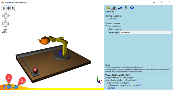
An XAML Viewer can be used, such as the Viewer3DS di AB4D to verify whether the XAML file containing the 3D model can be imported and displayed correctly in Movicon.NExT. |
|
The 3D graphics management is not supported during Web Client visualization.
|
Converting 3D files to XAML
Movicon.NExT has not yet been designed to change or create 3D graphics models directly within the development environment. Therefore, 3D graphics will need to be converted into XAML before importing them.
Before exporting the 3D model, check that the names of the layers do not contain special characters such as hatches, and exclamation marks. In addition, try to avoid using overly detailed geometries at polygonal mesh level (e.g. screws and bolts) which contribute to making the file too heavy to export.
This simplest way to do this is to:
Convert the 3D file to ".3DS" (Autodesk 3DS Max).
By means of using the Viewer3DS di AB4D software, open the ".3DS" file.
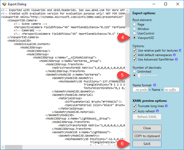
Select the XAML format for exporting file.

Make sure you select the "Viewport3D" option.
Lower the number of "Decimals" from Unlimited to Zero.
At this point you will be able to save the file in XAML format.

XAML File Structure for importing
If you wish to animate the elements of an imported 3D symbol, you will need to take precautions importing the ".xaml" file beforehand by adding the following tag in the initial code:
Tag = "ProblematicXamlWriter"
For example, if the original file has this structure:
<Viewbox x: Name = "MOV3DViewbox" ClipToBounds = "true" xmlns = "http://schemas.microsoft.com/winfx/2006/xaml/presentation"
xmlns: x = "http://schemas.microsoft.com/winfx/2006/xaml" xmlns: d = "http://schemas.microsoft.com/expression/interactivedesigner/2006"
xmlns: c = "http://schemas.openxmlformats.org/markup-compatibility/2006" c: Ignorable = "d">
.......
Simply add the tag as follows:
<Viewbox x: Name = "MOV3DViewbox" ClipToBounds = "true" xmlns = "http://schemas.microsoft.com/winfx/2006/xaml/presentation"
xmlns: x = "http://schemas.microsoft.com/winfx/2006/xaml" Tag = "ProblematicXamlWriter"
xmlns: d = "http://schemas.microsoft.com/expression/interactivedesigner/2006" xmlns: c = "http://schemas.openxmlformats.org/markup-compatibility/2006"
c: ignorable = "d">
.......
This precaution will ensure that the object's 3D animation functions correctly when imported by using the "Import XAML" command and inserted on screen from the Symbol Library using the "merge code" mode (incorporates code).
This ".xaml" file modification can be done with any text editor.
The WPF 3D technology offers the advantage of full use of the graphics acceleration hardware when available. As an alternative, WPF also provides fully automatic software rendering features that greatly simplify 3D management for the user so they won't need to use expensive hardware configurations or setups.
Importing 3D files on screen
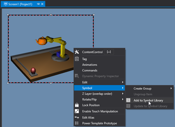
By using the "Import XAML" command available from the "Insert" group Toolbar, select the desired graphics file and import it into your project to create a new Movicon.NExT symbol.
Once the object has been imported on screen, select and group it using the CTRL+G command and then insert it in the project's customized symbol library.

|
From the file's browser window, make sure that you specify the file format ((filter selection). |
|
Attention! If you need to animate elements of an imported 3D file, insert the “ProblematicXamlWriter” tag in the symbol's code as indicated in the above paragraph on “Xaml file structure importing". |

3D elements in the Symbol Library
The Movicon Symbol Library contains some example 3D models that can be inserted in screens and used as needed. The user can also import their own 3D models as described previously, and save them in the symbol library to create their own custom 3D libraries by using the techniques described in the "Movicon Symbols" topic.
However, it is also possible to insert the ".xaml" file of the 3D object directly into the library folder for immediate use. For example, by appropriately arranging the "3DName.xaml" file of the object you wish to use, you can import the file directly by using the "Import XAML" command described above. This file can also be copied directly into the symbol library (for example in the path ".. \ Project1 \ Project1 \ Symbols \ 3DObjects" in order to insert the object in the project library).
Whatever mode you use, the 3D object can be made available in the library and inserted on screen using the "drop link" mode (drag connection) that "merges code" (incorporates the code).